OSPFv2 Interface Configuration (Config Museum)
The OSPF network command has confused Cisco newbies for decades. Today’s post looks at a more straightforward way to configure OSPF with a simple command to enable OSPF on each interface. To do so, we’ll do another Config Museum: a simple problem statement, and a place to practice. Plus, I’ll point to a resource to brush on the basics of how to configure OSPF without using the OSPF network command.
Aside: ICND2 Appendix B
For about three editions, I’ve included an “Exam Updates” Appendix in the back of the ICND1 and ICND2 cert guides. The purpose: If in the middle of an edition I want to add a little more content, I have a place to put it without touching the original chapters. We post the appendix online for free, and we even put it into print in the next printings of the books. All you have to do is go look for it.
For today’s topic, Appendix B now discusses how to configure OSPFv2 directly on interfaces. If you want to see what that Appendix says about this topic, just go to the book’s web page at Ciscopress.com, and look for the “Updates” tab. That page lists both the errata file and the latest version of Appendix B.
Now on to this week’s Config Museum!
Problem: Configure OSPF on Interfaces
As usual, this kind of post keeps things straightforward, just to give you a place to practice. This post begins with a network that has three routers, each with three configured interfaces, with all the interfaces working. The network has no IP routes other than the connected routes for each interface – that is, no routing protocol has been configured, and no static routes have been configured.
Your job: Enable OSPF on all three routers, with the following specifics:
- Do not use the network command in OSPF configuration mode.
- Put all interfaces in backbone area 0
- Assign each router an obvious OSPF router ID (eg, 1.1.1.1 for R1)
- Choose any other parameters you see fit, but….
- Do not configure any optional OSPF features other than what is needed to meet the requirements listed here.
Figure 1 shows the topology and IPv4 subnets, while Table 1 lists the router interfaces and IPv4 addresses for reference.
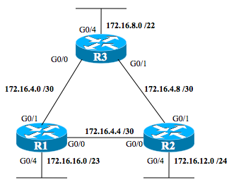
Figure 1: Router Triangle with Sample IP Addresses for Calculations
Table 1 lists the results of choosing the highest IP addresses, by router and interface:
| Location | IP | Mask |
| R1 G0/0 | 172.16.4.5 | 255.255.255.252 |
| R1 G0/1 | 172.16.4.1 | 255.255.255.252 |
| R1 G0/4 | 172.16.17.254 | 255.255.254.0 |
| R2 G0/0 | 172.16.4.6 | 255.255.255.252 |
| R2 G0/1 | 172.16.4.9 | 255.255.255.252 |
| R2 G0/4 | 172.16.12.254 | 255.255.255.0 |
| R3 G0/0 | 172.16.4.2 | 255.255.255.252 |
| R3 G0/1 | 172.16.4.10 | 255.255.255.252 |
| R3 G0/4 | 172.16.11.254 | 255.255.252.0 |
Table 1: IP Addresses and Locations
Try This at Home!
Also, note that the lab topology uses particular router interfaces on purpose. If you download Cisco’s All-in-One VM, the network simulator that comes with AIO (for free) implements this same topology. To do so, you just have to start the default topology, and then the routers’ G0/3 interfaces. For more detail, check out this earlier post, part of a series about the AIO VM, VIRL. Also, note that since the time I wrote that earlier post, Cisco released a personal edition of VIRL – I’m sure you could try this lab with VIRL as well.