Answers: FR DLCI Drill #1
This is the answers post – to make the most sense of it, read the original question post listed here. This post is about how to look at figures, sift through the documentation about Frame Relay DLCIs, and predict the DLCIs used when each device forwards Frame Relay frames.
Also, note that this is one of the topics I improved in the new 3rd edition of the ICND2 Official Cert Guide (as compared to the previous edition). Both books discuss these details, but the newer one spells it out a little better. Enjoy, and ask questions if you have them! Also, if you find this topic useful, check out this related lab.
Documentation: Steps 1 and 2
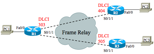
Step 1 in each FR drill asks you to figure out whether the initial figure shows global or local DLCIs. Then at step 2, you turn the figure around, showing it with the opposite style. Figure 1 in this post repeats that original post’s Figure 1.
In this drill, the original figure showed global DLCIs. How do you know? Global DLCI actually defines a documentation and DLCI assignment convention used by the service provider. The documentation lists a single number as the DLCI for a link connected to the FR network, even if multiple PVCs connect through that link. If a link has >1 PVC, but only one DLCI listed, the figure either shows global DLCIs, or it left out some numbers. (I assumed that the docs were complete for our purposes with this exercise.)
Figure 1 – Initial Documentation, FR Drill 1 – Global DLCI
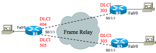
At step 2, you need to create a new figure that shows local DLCIs. To do so, start with a new figure, with the same topology, but with no DLCI values. Then take the original global DLCIs, and for each PVC, write down the global DLCI on the opposite end of the PVC from where it was listed originally. For instance, R1 in Figure 1 shows global DLCI 303, with two PVCs. In the local DLCI figure, write “303” beside the PVC connected to R1 but on the R2 end, and also on the PVC connected to R1 but at the R3 end. Figure 2 shows the completed work to document the local DLCIs.
Figure 2 – Revised Documentation – Local DLCI
Encapsulation: Steps 3 and 4
At step 3 you have to predict the DLCI values that will be in the headers as the frames pass over the various links. The key concepts at this point are that over each link, the frame lists the local DLCI. The FR network actually swaps the DLCI values as the frame passes through the FR network.
Another way to think about it that gets even closer to the task at this step are these two summary statements:
- When a router sends a frame, the frame lists the sending router’s local DLCI for the PVC
- When a router receives a frame, the frame lists the receiving router’s local DLCI for the PVC
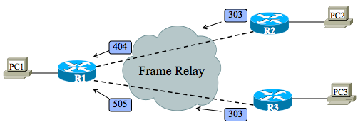
Figure 5 shows the results of the encapsulation from left to right. When R1 sends to R2, R1 sends with its local DLCI for that PVC, or 404, but when the frame arrives at R2, the frame lists R2’s local DLCI for that PVC, or 303. Similarly, when R1 sends to R3, the sent frame lists DLCI 505, but R3 receives a frame with DLCI 303. Figure 6 shows the flow in the opposite direction.
Figure 5 – DLCIs in Left-to-Right Flow
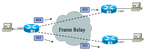
Figure 6 – DLCIs in Right-to-Left Flow
That’s it! Ask questions if you have them.