Free Play Labs – CCNA Vol 1 Chapter 20
For many years, over many different versions of the CCNA exam, Cisco included multiple IP routing protocols in the exam: RIP, OSPF, EIGRP, and even BGP. With CCNA 200-301, Cisco reduced IP routing protocols down to only one: OSPF. Chapter 20 of the CCNA 200-301 Volume 1 Cert Guide looks at the basics of configuring OSPF, with this post working through some details to help you re-create Chapter 20’s examples.
Confused? New to “Free Play” Labs?
The idea is simple: Many students would like to further explore the Examples in the Official Cert Guide. We remove the barriers so you can do just that with the free Cisco Packet Tracer simulator.
The details require some reading. To get your head around what kind of content is here in the blog for these labs, read:
Book: CCNA 200-301 OCG, Volume 1
Chapter: 20
Title: Implementing OSPF
Part: 6
What’s in This Post
Chapter Intro: A brief description of the topics in that chapter of the book.
Download Link: Links to a ZIP; the ZIP holds all the .PKT files for this chapter.
Table of PKT files, by Example: A table that lists each example in the chapter, with the files supplied for each. Also lists a note about whether the PKT topology matches the book example exactly or not.
Tips: When we build the files, we come across items that we think might confuse you when trying the examples with PT. We write those notes in this section!
Chapter Intro
To make OSPF work, you need to configure each router to enable OSPF on all the necessary interfaces, assigning each interface to the correct OSPF area. That covers the requirements. Additionally, you may want to configure several optional settings as well. This chapter touches on the required settings as well as several optional settings. The configuration items include:
- Enabling OSPF on interfaces using network commands in OSPF configuration mode
- Enabling OSPF on interfaces using ip ospf commands in interface configuration mode
- Setting the OSPF Router ID in various ways
- How to configure different interfaces in different OSPF areas
- How to configure passive interfaces, default routes, and how to influence OSPF metrics
This chapter has a fairly large number of examples so there should be plenty to learn with Packet Tracer. Enjoy!
One .PKT File – But Maybe Two (Duplicate) Toplogies
When building the content for this post, we review the examples in the book and decide whether it makes sense to supply a Packet Tracer (.pkt) file to match the example. If we choose to support an example by supplying a matching .pkt file, the .pkt file includes a topology that matches the example as much as possible. It also includes the device configurations as they should exist at the beginning of the example.
In some cases, the .pkt file shows two instances of the lab topology – one above and one below. We include two such topologies when the book example includes configuration commands, for these purposes:
- Top/Initial: The topology at the top has the configuration state at the beginning of the example.
- Bottom/Ending: The topology at the bottom adds the configuration per the example, so that it mimics the configuration at the end of the example.
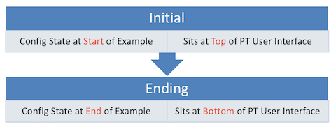
Table of .PKT Files, by Example
| Example | .PKT Includes Initial State of Example? |
.PKT Also Includes Ending State of Example? |
Exact Match of Interface IDs? |
| 20-1 | Yes | Yes | Yes |
| 20-2 | Yes | Yes | Yes |
| 20-3 | Yes | Yes | Yes |
| 20-4 | Yes | No | Yes |
| 20-5 | No | No | Yes |
| 20-6 | No | No | Yes |
| 20-7 | No | No | Yes |
| 20-8 | No | No | Yes |
| 20-9 | Yes | Yes | Yes |
| 20-10 | Yes | No | Yes |
| 20-11 | Yes | Yes | Yes |
| 20-12 | Yes | Yes | Yes |
| 20-13 | No | No | Yes |
| 20-14 | No | No | Yes |
| 20-15 | Yes | Yes, A and B | Yes |
| 20-16 | Yes | No | Yes |
| 20-17 | Yes | Yes | Yes |
| 20-18 | Yes | Yes | Yes |
Tips
Note that Examples 20-1, 20-2, and 20-3 build the IP address and OSPF configuration on four routers.
Examples 20-1, 20-2, and 20-3 build the IP address and OSPF configuration on four routers.
Note that the first printing of the book listed Example 20-2 as being the configuration for router R2, but it should have listed it as the configuration on R2. The PT file supplied here adds the Example 20-2 configuration to router R1.
Examples 20-1, 20-2, and 20-3 build the IP address and OSPF configuration on four routers.
Note that the book’s first printing contained two related errors in this example: The two references to “VLAN4” should instead have listed “GigabitEthernet0/1”. Also, note that the example is about router R4 (the book’s caption refers to R1 instead of R4.)
Note that while this example begins with some configuration commands, earlier Example 20-3 already included those same commands. So, the initial configuration of the PT file already includes the configuration in this eample.
Output of show ip protocols command in PT differs slightly versus the real gear used to generate the output for the book. The output in the Example comes from router R3, with OSPF RID 3.3.3.3. PT lists 3.3.3.3 as a routing information source, whereas the example does not. Real Cisco gear would not include 3.3.3.3 in this case.
PKT does not except the brief option. Uses can use show ip ospf interface and look through the output to find the information needed.
This example in the book shows some of the ways you can configure OSPF router IDs (RIDs) to match the results shown in the previous four examples.
The example lists the output of the show ip protocols command, to some extent focusing on the section titled “Routing on Interfaces”. Note that PT does not include that same section of output in the version of PT (7.3) used when we created this exercise.
The text in the example in the book highlights the “Attached via Interface Enable” phrase. However, note that PT (in the version we used when creating this post) does not support the “Attached via interface” part of the output.
The example lists two alternative configurations, so we supplied two PT files. The file ending in “A” uses the configuration in the top half of the example, and the file ending in “B” uses the configuration in the bottom half.
PT does not support the brief option on the show ip ospf interface brief command, but you can use the command without the brief keyword to find more detailed information.
I just purchased CCNA 200-301 and early in the ebook, there is a link to this website. In this case, was able to download the PKT.zip and open the files in packet tracer. But, where are the labs? Usually in the past there would be a lab that would open up and required to follow the lab? Is there a seperate book. Plus the chapters here, such as Chapter 20 do not match the book? Confusing.
Paul,
Sorry you found it confusing. Let me clarify.
First, go to the heading near the top of the post, the one that begins “Confused”. There’s a link there to the page that explains what this series of posts is about. Short version: A post like this one helps you re-create the examples in the book. These posts are not separate lab exercises.
As for your comment about this post not matching chapter 20 of the book, I’m confused as well. This post provides Packet Tracer files to help you re-create the examples from Chapter 20 of the CCNA Vol 1 book. Maybe the page linked above is enough to connect the dots.
Hope this helps!
Wendell
Yes master. Yes. Master. I will not makes that mistakes again.
Hi Wendell
I’m finally at chapter 28 of the first book and it’s now at the point of configuring a WLC in a browser. What’s the best way for me to setup a lab to set this up and practice setting up a WLAN?
Thanks
Greg
good day wendell
i’ve downloaded this PKT file and i’m using the latest version of packet tracer and when try to use (sh ip ospf interface brief ) command, it doesn’t work or accurately it’s not included in the list of sh commands! what should i do to fix this ?
Hi Basem,
Within Packet Tracer, the answer is that you and I can’t do anything. It’s a simulator, which means that it does not 100% act like real gear and real Cisco operating systems. PT does not support the “brief” option on the command. (See the accordion table at the end of the post, EG, for example 20-8.) I try to point out such PT issues in the tips table at the bottom of each of these posts.
An actual fix would be to get at least a couple of used routers and switches, or use VIRL or GNS3. https://www.certskills.com/lab/
Wendell
I would like to clarify a paragraph that’s in Chapter 20. In page 493 of Volume 1 book of 200-301 book you mentioned that using reference bandwidth of 100000 (aka 100Gbps), you would get a cost of 4 using a 40Gb link. Did you make a typo here or do I not fully understand how reference bandwidths work?
100000/40000 is 2.5 which would be truncated to 2, hence the cost should be 2 instead of 4 (according to my calculations).
Could you please confirm this?
Hi Barnabus,
It’s a mistake, pure and simple. Your logic is 100% correct. I’ve noted the mistake in the errata file that’s next in line to be published. Thanks for taking the time to let me know!
Wendell
Hi Wendell,
Im confused on the Table 20-3 Book Volume 1
Gigabit Ethernet = 1 cost
10 Gigabit Ethernet = 1 cost
100 Gigabit Ethernet = 1 cost
is it true?
or should be;
Gigabit Ethernet = 10 cost
10 Gigabit Ethernet = 100 cost
100 Gigabit Ethernet = 1000 cost
for verification only. Thanks!
The cost of 1 for 1Gbps, 10Gbps & 100Gbps is correct based on the default OSPF reference bandwidth of 100Mbps. The formula for OSPF cost is reference bandwidth divided by the interface bandwidth (reference bandwidth/interface bandwidth). Any result that is less than 1 is rounded up to 1. So…
10 Mbps is 100/10 =10
100 Mbps is 100/100 =1
1Gbps (1000 Mbps) is 100/1000 =0.1 and is rounded up to 1
10Gbps (10,000Mbps) is 100/10000 =0.01 and is rounded up to 1
…and so on.
The recommended “fix” for this is to change the reference bandwidth with the command “auto-cost reference-bandwidth [value in Mbps] to a number that is higher than the fastest link in the network. The command “auto-cost reference-bandwidth 1000000 for example would result in the following cost values…
10 Mbps is 1000000/10 =100,000
100 Mbps is 1000000/100 =10,000
1Gbps (1000 Mbps) is 1000000/1000 =1,000
10Gbps (10,000Mbps) is 1000000/10000 =100
100Gbps (100,000Mbps) is 1000000/100000 =10
…and so on.
Jaime,
Sorry for not replying earlier. I know I typed a reply, but I’m having weird problems getting WordPress to take the comment reply. Anyway, Steven K’s reply answers fully and clearly. FYI.
Hi Wendell, I am re-reading page 476. in the example output it list from R1 that R4 is FULL/BDR – but i am having a hard time clarifying this… As I believe it should be the DR, i’ve downloaded you PKT also and cannot see it listed as BDR in any of them, is this a misprint / error? if not, can you explain why R4 from R1 became BDR in the example output (20-4) please?
Hi John,
Honestly, I should change the example as you say. But as it turns out, the example text is correct. Let me explain.
First, you are correct in that when an election occurs on the R1-R4 link, R4 will win, and be the DR. So R1 should list R4 as DR, not BDR.
However, in real gear, note that DR/BDR election does NOT preempt the existing DR or BDR. So, consider this sequence:
1) R1’s WAN interface reaches up/up; R1 becomes DR; R4’s WAN interface later comes up; R4 becomes BDR.
Or:
2) R1 and R4 initialize at the same time, R4 becoming DR; R4’s OSPF process is shutdown; R1 becomes DR; R4’s OSPF process is then “no shutdown” to bring it up again; R4 becomes BDR.
For this example, I used output to talk about the meaning of the fields. But it would be better to show cases in which the results match what happens when an election happens, and defer the above logic until later when I get more into DR election. I’ve made a note to that effect.
Finally, I tried to force R4 to be the BDR in Packet Tracer, and couldn’t do it. But I was able to do the equivalent on real gear in scenarios 1 and 2 above just now. FYI.
Wendell
Hi – example 20-4 show that 4.4.4.4 is the BDR from R1 – from what i understand this is not right? is this a typo? if not, Im having a hard time finding out why 4.4.4.4 would be the BDR considering it has a higher RID?