Free Play Labs – CCNA Vol 1 Chapter 24
Doing labs helps you move from book-knowledge to real skills, and doing labs that repeat the same examples found in the book can be a great bridge to that effort. This next post continues our series to help you do just that by giving you a good starting point in Cisco Packet Tracer from which to re-create the CCNA Official Cert Guide’s many examples. Today’s post summarizes the assistance with CCNA 200-301 Volume 1 Chapter 24: Implementing IPv6 Addressing on Routers.
The chapter introduces the commands to configure IPv6 addresses on Cisco routers. If you have not already done so, you will need to read Chapters 22 and 23 as well, which give the related conceptual background, with Chapter 24 focusing on implementation details on Cisco routers.
Confused? New to “Free Play” Labs?
The idea is simple: Many students would like to further explore the Examples in the Official Cert Guide. We remove the barriers so you can do just that with the free Cisco Packet Tracer simulator.
The details require some reading. To get your head around what kind of content is here in the blog for these labs, read:
Book: CCNA 200-301 OCG, Volume 1
Chapter: 24
Title: Implementing IPv6 Addressing on Routers
Part: 7
What’s in This Post
Chapter Intro: A brief description of the topics in that chapter of the book.
Download Link: Links to a ZIP; the ZIP holds all the .PKT files for this chapter.
Table of PKT files, by Example: A table that lists each example in the chapter, with the files supplied for each. Also lists a note about whether the PKT topology matches the book example exactly or not.
Tips: When we build the files, we come across items that we think might confuse you when trying the examples with PT. We write those notes in this section!
Chapter Intro
It almost seems too simple: Just configure a global unicast IPv6 address for each interface, using the ipv6 address interface subcommand. This chapter revolves around what happens when you configure that interface subcommand on each interface, but it takes a chapter because of a variety related happenings when you add that configuration:
- The router enables IPv6 on the interface.
- The router dynamically creates a link-local IPv6 address for the interface – an address that can be affected by other configuration.
- The router begins using different IPv6 multicast addresses depending on other IPv6 features on the router.
In addition to these base features, you have the option to ask the router to dynamically learn its IPv6 global unicast address, or to even avoid global unicast addresses altogether, relying solely on a link-local address for an interface.
As you can see from this brief introduction, IPv6 address configuration quickly moves from the process of assigning each router interface an address to the intricacies of IPv6. Enjoy!
One .PKT File – But Maybe Two (Duplicate) Toplogies
When building the content for this post, we review the examples in the book and decide whether it makes sense to supply a Packet Tracer (.pkt) file to match the example. If we choose to support an example by supplying a matching .pkt file, the .pkt file includes a topology that matches the example as much as possible. It also includes the device configurations as they should exist at the beginning of the example.
In some cases, the .pkt file shows two instances of the lab topology – one above and one below. We include two such topologies when the book example includes configuration commands, for these purposes:
- Top/Initial: The topology at the top has the configuration state at the beginning of the example.
- Bottom/Ending: The topology at the bottom adds the configuration per the example, so that it mimics the configuration at the end of the example.
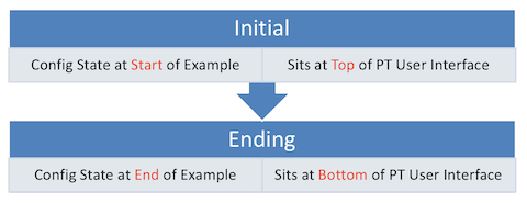
Table of .PKT Files, by Example
| Example | .PKT Includes Initial State of Example? |
.PKT Also Includes Ending State of Example? |
Exact Match of Interface IDs? |
| 24-1 | Yes | Yes | Yes |
| 24-2 | Yes | Yes | Yes |
| 24-3 | Yes | No | Yes |
| 24-4 | use 24-3 | No | Yes |
| 24-5 | Not Supplied | Not Supplied | N/A |
| 24-6 | Not Supplied | Not Supplied | N/A |
| 24-7 | Not Supplied | Not Supplied | N/A |
| 24-8 | Yes | No | Yes |
| 24-9 | Yes | No | Yes |
| 24-10 | Yes | Yes | Yes |
Tips
Examples 24-1, 24-2, and 24-3 build in sequence.
Example 24-1 uses the following for the initial state part of the topology:
- The PT file supplies the same topology used in the examples.
- The initial state has all working interfaces, with no IPv6 addresses configured on either router.
The bottom part of the Example 24-1 topology shows the ending state, which includes the configuration commands as listed in Example 24-1 (router R1.)
Examples 24-1, 24-2, and 24-3 build in sequence.
Example 24-2 begins with the ending state of Example 24-1:
- The PT file supplies the same topology used in the examples.
- The initial state has all working interfaces, with R1’s IPv6 addresses configured per Example 24-1.
The bottom part of the Example 24-1 topology shows the ending state, which includes the configuration commands as listed in Example 24-2.
Examples 24-1, 24-2, and 24-3 build in sequence. For Example 24-3, just open the PT file and issue any show commands. The PT file begins with the configuration as listed in earlier examples 24-1 and 24-2.
Like Example 24-3, Example 24-4 lists output based on the configuration in Examples 24-1 and 24-2. So, just use the PT file for Example 24-3.
Packet Tracer performs the EUI-64 address calculation incorrectly. Examples 24-5, 24-6, and 24-7 examine addresses that use EUI-64, so we did not provide PT files, given that PT calculates incorrect values.
Just so you know the issue:
- PT sets the 7th bit of the interface ID to binary 1 when performing EUI-64 conversion. That is, the bit is always a 1 at the end of the process.
- Real devices invert the 7th bit of the interface ID when performing EUI-64 conversion. That is, if originally a 0, the bit is inverted to a 1; if originally a 1, it is inverted to a 0.
PT does not accept the command show running-config interface f0/2, as shown in the book example. Use show running-config and scroll to interface f0/2 instead.
The example does not refer to any figure in the book, but instead focuses on a single device and the configuration on that device. To support that work in PT, we created a simple network, with the work done in router R1.
PT does not accept the command show running-config interface f0/2, as shown in the book example. Use show running-config and scroll to interface f0/2 instead.