Answer to a Question with STP, 802.1Q, ARP, and MAC tables
I got started on this discussion of the previous post’s sample question based on a question from a reader of the ICND2 Cert Guide. For the discussion of the answers, I’d like to focus on the one answer that makes you think about both layer 2 and layer 3 forwarding to answer the question: Answer E. For today’s post, I’ll discuss some of the reasoning around that one answer, and I’ll hide the letter answers to the question somewhere near the end of the explanation so to avoid spoiling the answer if you’ve not yet gotten to read the question.
Layer 3 Set-Up Based on the Question/Figure
Answer E asks specifically about a ping, done on PC2, with destination PC3. And, the question specifically mentions the ICMP Echo Request, which means we only care about the IP packet carrying the ICMP Echo Request from PC2 to PC3, and not the return IP packet holding the ICMP Echo Reply message, which flows from PC3 to PC2.
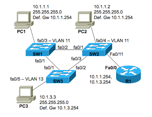
Next, the figure shown with the question, but not the question text, tells us enough info to know that PC1 and PC2 are in the same VLAN and subnet, and that PC3 is in a different subnet. The relevant facts:
- PC1’s IP address is 10.1.1.1; PC2’s is 10.1.1.2, both with mask 255.255.255.0. The subnet math with both puts them in subnet 10.1.1.0/24.
- PC1 and PC2 has the same default gateway (10.1.1.254), which is listed by router R1
- PC3’s IP address/mask, 10.1.3.3 and 255.255.255.0, put it in subnet 10.1.3.0/24, a different subnet
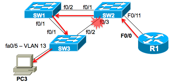
- The figure also shows PC2’s and PC3’s switch ports as being in different VLANs (11 versus 13).
Figure 1 repeats the same figure from the question, for reference.
Figure 1: Original Problem’s Figure
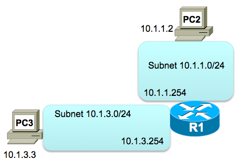
Finally, the question also mentioned the details related to router R1 as the default gateway. The question mentions that R1 uses 802.1Q trunking. The figure shows the router with two IP addresses beside its F0/0 interface, and finally, both PC2 and PC3 list a default gateway setting pointing to one of those R1 IP addresses. As a result, the question tells us that the layer three topology looks like Figure 2:
Figure 2: Layer 3 Topology with Default Gateway
Layer 3 Analysis of IP Packet Flow
Moving on to the analysis piece of the puzzle, when PC2 needs to send its IP packet, it may or may not need to ARP. However, answer E does not ask about ARP, nor do any of the other answers, so for this question, ignore the ARP.
When PC2 sends the ICMP Echo Request, from a layer 3 perspective, PC2 thinks like this:
10.1.3.3 is in a different subnet them me, so send this packet to my default gateway (router)
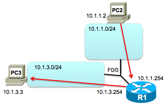
Once the IP packet arrives at R1, R1 routes the packet, back out the same physical F0/0 interface, but now onto subnet 10.1.3.0/24 (aka VLAN 13 at layer 2). Figure 3 shows the layer 3 perspective, ignoring the layer 2 details:
Figure 3: Layer 3 Flow, ICMP Echo from PC2 to PC3
Layer 2 Analysis of IP Packet Flow
Now, back to the Question, and answer E. Answer E asks whether the ICMP Echo Request flows through SW1 at any point. The ICMP Echo Request has to flow through both SW2 and SW3, because we know 1) the ping worked and 2) PC2 connects only to SW2 and 3) PC3 connects only to SW3. But do SW2 or SW3 ever forward the frames over to SW1?
From the previous section’s layer 3 analysis, we know that PC2 does not just send an IP packet directly to PC3; instead, PC2 sends the packet to R1. To do that, PC2 sends the IP packet inside an Ethernet frame, through VLAN 11, with R1’s MAC address as the destination MAC address. Then, R1 makes an IP routing decision, encapsulating the IP Packet (which holds the ICMP Echo Request) over VLAN 13 to PC3. So, from a layer 2 perspective, we have the following two Ethernet frames that hold the encapsulated ICMP Echo Request:
- PC2’s Ethernet frame sent to R1’s MAC address, in VLAN 11
- R1’s Ethernet frame sent to PC3’s MAC address, in VLAN 13
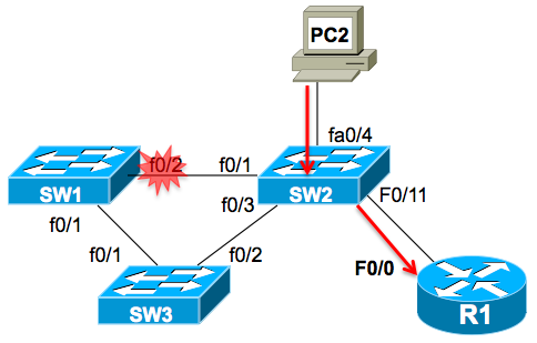
To see where the frames will flow, you have to look at the STP topology, and find where STP has blocked. The question statement identified the blocked ports. Figure 4 shows the block in VLAN 11, with the frame flow for the frame sent by PC2 to R1 (its default gateway). As you can see, it does not flow through switch SW1.
Figure 4: STP Topology in VLAN 11 and Frame Flow to R1
The more interesting part of the discussion, and the part that finally tells us that Answer E is correct, is the flow inside VLAN 13. In this case, SW2 blocks on its interface connected to SW3. As a result, the only available path for learning PC3’s MAC address, and for forwarding frames to PC3, connects from SW2, to SW1, and then to SW3, as shown in Figure 5.
Figure 5: STP Topology in VLAN 13 and Frame Flow to PC3
Spoiler Alert: Answers
Finally, to close… the answers are:
.
.
.
.
.
A, D, E
.
.
.
.
.
.
.
Suppose that, in a typical triangle STP topology (just three switches), using IEEE802.1D STP , you have a non-root switch
with one of its ports in a blocking state (that implies that it is connected to the designated switch on its designated port).
This non-root switch (and non-designated switch either) lost communication to root switch through its root port.
Blocked port is still recieving BPDU’s from the designated switch (which is still directly connected to
root switch).
¿How long will it take to that blocked port transiotioning to forward state as a new root port?
As far as I know a blocked port transitions to forward state just when it stop hearing betters or equals BPDU’s.
In the scenario I describe it still is hearing the same BPDU’s from the designated switch.
Is there a IEEE802.1D STP rule that I’m missing?
Hector, to root port, the transition from the blocked state to forwarding state takes time. It transitions immediately at that point to a listening state, where it sits for Forward Delay time (default 15 seconds). Then it transitions to Learning state for another Forward Delay time, and then transitions to Forwarding.
Look at pages 55-57 of the ICND2 book for more detail. Shorter version:
Max Age time must pass without receiving the formerly best (aka “superior”) Hello before acting. Unless a more obvious event, like link failure on the root port, occurs.
Then, once the non-root switch decides to move a port’s role from
So, with a typical default of 20 seconds for Max Age, if the switch needs to wait for Max Age, it’s about 50 seconds to converge.
Wendell
Thanks. My confusion was because of the fact that despite the non-designated root port stops hearing BPDUs, the blocked one
(the one who MUST TRANSITION to forward state) IS STILL hearing the SAME BPDU from the designated switch (so the “worse BPDU” rule over this port would not be complied).
So, I deduce that, no matter which port stops hearing or recieves a worse BPDU, this will make the blocked port transition to forward state, upon the following conditions:
– if the root port does not recieve at least the same BPDU it was recieving, the transition process is triggered
– if the blocked port recieves a worse BPDU than it was receiving, the transition process is triggered
Question number #1: Is it like I’ve just described?
Question number #2: Does a non-designated switch blocked port RECIEVING a better BPDU than the one this switch recieves on its root port, make that blocked port transitions to forward state? If it is so, ¿does transitioning process take the same time that takes
when the blocked port recieves a worse BPDU (throughout all STP states)?
Question number #3: Is a blocked port just listening BPDUs?
Question number #4: Which STP states allow BPDU sending?
I hope I had made it clearer than my previous comment. Sorry for that bunch of questions.
Thanks on advance.
By the way, I’ve just submitted a comment and it is not shown above
Hector,
Sorry about that. The short version is that the spaminator plugin I’m using requires approval of a few comments before it’ll show your posts without approval, which cuts down on the spam quite a bit. I get lots of advertising spam attempts to the blog here, so I have to keep the filters up pretty high. Hoping to be quicker on the approvals this calendar year!
Your questions always get me sweating, expectantly when i don’t see there was three correct answers, lol.