Answers: FR DLCI Drill #2
This is the answers post – to make the most sense of it, read the original question post listed here. As with the other FR DLCI drills, this post provides an exercise of how to look at figures, sift through the documentation about Frame Relay DLCIs, and predict the DLCIs used when each device forwards Frame Relay frames. The answer is below the fold, with a few related links above the fold:
Read more about this topic in the new 3rd edition of the ICND2 Official Cert Guide
Documentation: Steps 1 and 2
Step 1 in each FR drill asks you to figure out whether the initial figure shows global or local DLCIs. Then at step 2, you turn the figure around, showing it with the opposite style. Figure 1 in this post repeats that original post’s Figure 1.
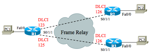
This drill started with local DLCIs in Figure 1. How do you know? Local DLCI documentation lists a DLCI beside each end of each DLCI. In contrast, when one router has >1 PVC connected through one serial link, the Global DLCI convention lists the one global DLCI beside that router. The Figure 1 for this FR drill clearly lists 1 DLCI per end per PVC.
To quickly figure out which type of DLCI documentation a figure uses, look for a router with more than 1 PVC crossing a single link. If that link shows one DLCI, the figure shows global DLCIs; if one DLCI per PVC, it shows local DLCIs. In this drill, R1 has two PVCs crossing one link in the original Figure 1.
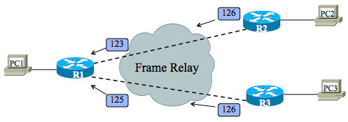
Figure 1 shows the original figure for reference, with the local DLCIs.
Figure 1 – Initial Documentation, FR Drill 2 – Local DLCI
At step 2, you need to create a new figure that shows global DLCIs, if possible. (It is possible in this case.) I’ll describe one way to do it, although you do not need to memorize a particular process.
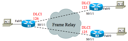
Start with a new figure, with the same topology, but with no DLCI values. Then look at the original local DLCIs, and for each PVC, write down the local DLCI on the new figure, but not in the same place. Write it down on the other end of the PVC. Also, write the word “global” beside it as a reminder.
When you have done that for every PVC, for every local DLCI, some routers will have multiple notes of “Global zzz” beside it. If each router lists one number for all the “global zzz” notes, then the design follows the global DLCI convention as well, and you can clean up the figure.
Figure 2A shows an interim version of the figure, with two notes of “Global DLCI 123” beside router R1. Figure 2 shows the cleaner figure that lists global DLCIs as usual, with a single DLCI beside each router.
Figure 2A – Interim Version, Global DLCI
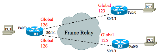
Figure 2 – Final Version, Global DLCI
Encapsulation: Steps 3 and 4
At step 3 you have to predict the DLCI values that will be in the headers as the frames pass over the various links. The key concepts at this point are that over each link, the frame lists the local DLCI. The FR network actually swaps the DLCI values as the frame passes through the FR network.
Another way to think about it that gets even closer to the task at this step are these two summary statements:
- When a router sends a frame, the frame lists the sending router’s local DLCI for the PVC
- When a router receives a frame, the frame lists the receiving router’s local DLCI for the PVC
Figure 5 shows the results of the encapsulation from left to right. When R1 sends to R2, R1 sends with its local DLCI for that PVC, or 123, but when the frame arrives at R2, the frame lists R2’s local DLCI for that PVC, or 126. Similarly, when R1 sends to R3, the sent frame lists DLCI 125, but R3 receives a frame with DLCI 126. Figure 6 shows the flow in the opposite direction.
Figure 5 – DLCIs in Left-to-Right Flow
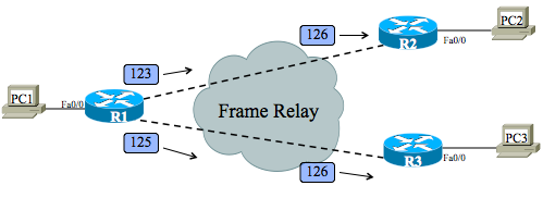
Figure 6 – DLCIs in Right-to-Left Flow
That’s it! Ask questions if you have them.